CIVIL WORKS GUIDELINES FOR MICRO-HYDROPOWER IN NEPAL
133
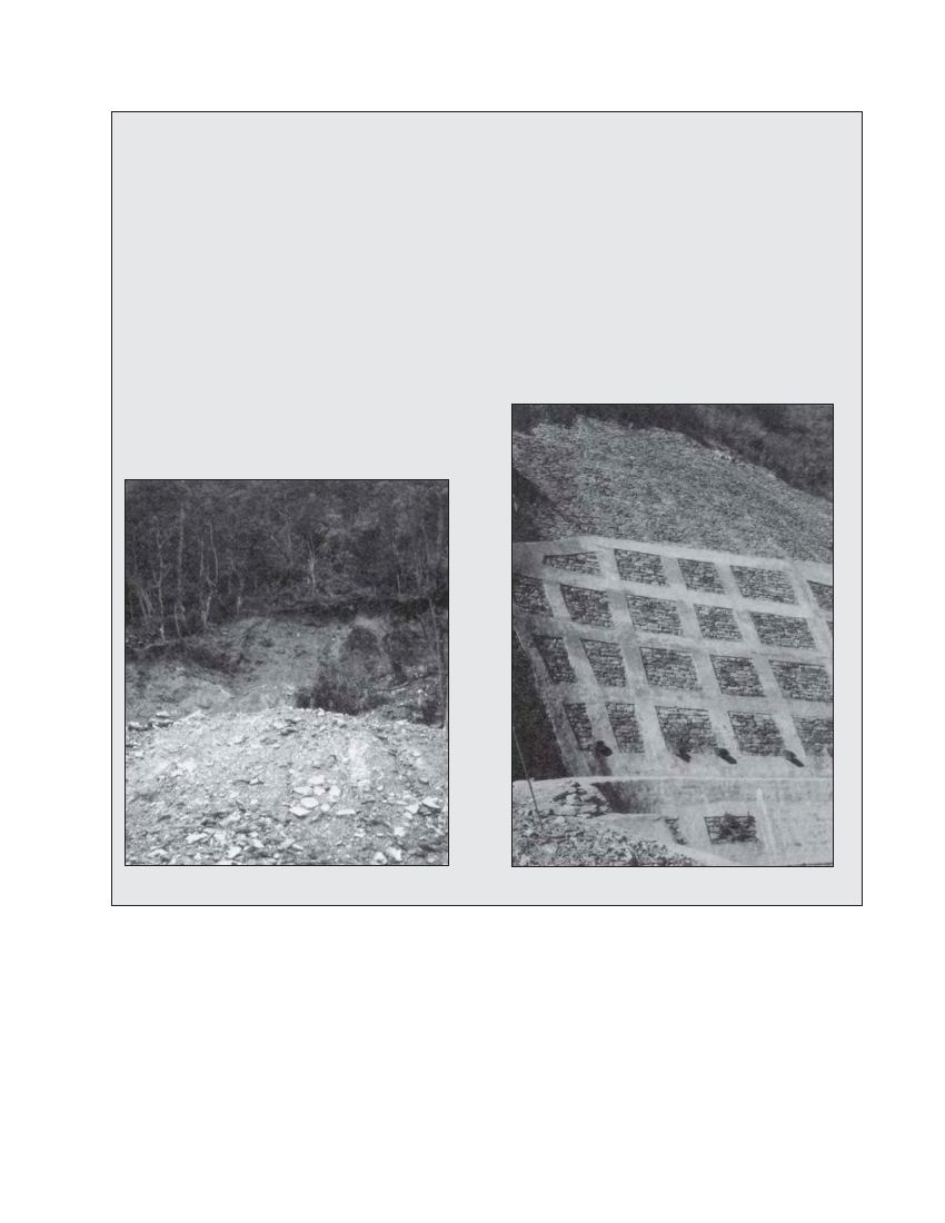
Box 9.1 Use of masonry grid to stabilise the jhankre mini-hydro powerhouse area slope
In order to increase the gross head of the Jhankre mini-hydro scheme, it was decided to excavate a 20 m depth at the power-house
area. This required stabilising the hill slope behind the powerhouse area. This area also had to drain ground water due to seepage
from the cultivated terraces (paddy fields) above. When irrigation water was provided for the paddy fields significant seepage was
observed at the powerhouse area. After considering various alternatives, it was decided to use a grid of masonry beams and
columns infilled with dry stone panels. Photographs 9.5 and 9.6 show the hillside during excavation and after the construction of the
masonry grid.
The hill slopes were first excavated at 2:1 to 3:1 slopes (V:H) with two intermediate berms along the hillslope and one at the sides.
Then the grid of stone masonry (in 1:4 cement: sand mortar) beams and columns with dry stone masonry infill panels was
constructed along the excavated slopes. The beams and columns are 500 mm wide and 300 mm deep. The distance between the
columns is 2 m and the vertical distance between the beams is 1.5 m (maximum). The dry stone infill saved the cost of cement and
facilitates drainage. Catch drains have been provided at the berm levels.
To date this 16 - 20 m high structure is stable. During the monsoon
ground water that has seeped from the paddy fields above can be
seen draining out from the weep holes and the dry stone panels.
Photo 9.5 Excavated slope at powerhouse
Photo 9.6 Masonry grid at powerhouse slope
9.6 Check dams and gully control
Gullies that are active or small streams where scouring of the
riverbed is prominent can be controlled by constructing check
dams. Check dams are small walls that prevent further erosion
on the watercourse and also allow deposition of bed load
upstream of it at a stable gradient. For small gullies that are
only active during the monsoon, the check dam could consist
of a simple dry stone wall. For small streams, bed erosion can
be controlled by using gabion check dams.
Gabion check dams have been used to control riverbed
scouring at the Jharkot micro-hydro scheme. The riverbed at
the Jharkot intake area had been scoured by more than 3 m at
some places and the scour depth was getting deeper. It was
felt that further scouring along the riverbed would cause total
failure of the existing gabion wall along the left bank of the
river. A series of gabion check dams was constructed at the
intake area to prevent further scouring and to facilitate the
deposition of bed load. The first check dam is shown in Fig-ure
9.4. Note that to prevent the gabion wires from being broken